The machine was taken apart for service, so I had a chance to take a closer look at the interior of it.
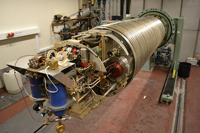
The machine is of the KN type. On the picture above you can see the pressure tank which is filled with a mixture of nitrogen and SF6 for spark suppression.
The terminal cap is removed, exposing the interiors.
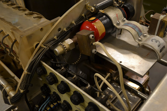
This is the ion source. The copper tube at the top leads the gas to be ionized into the glass tube. RF connectors for ionizing the gas are detached here. The red cylinder to the right is a solenoid which provides some focusing of the beam.
RF power generator.
The red gas container is filled with deuterium gas. It can be used for neutron production, e.g. by bombarding beryllium targets with a beam of deuterium ions.
But mostly, proton and helium ion beams are required. The two blue gas containers shown here hold hydrogen (left) and helium gas (right).
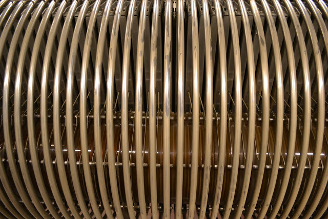
In order to achieve a good beam, it is important to maintain a regular voltage gradient from the terminal to the base which is on ground potential. The dark green columns inside the metal rings are high voltage resistors.
The accelerator is not in too good condition. The dust which can be seen here (and everywhere) is from the rubber belt which delivers the charge to the terminal.
The last time I tried to operate the accelerator, the maximum voltage achievable was 2.3 MV. This is sufficient for most experiments done here which deal with radiation induced defects in silicon.
The accelerator seen from the other side, the terminal cap in front.
The terminal cap of the accelerator. If you zoom in, you can see plenty of markings from high voltage sparks which happen from time to time.
This is the high energy end of the accelerator. The beam tube is that vitreous thing in the middle going from the left to the right. Notice how clear the glass is on this end...
... but as we get closer to the terminal, the glass darkens...
... and at the ion source, the glass is dark brown. I presume the explanation is that the accelerator mostly runs with positive charge for accelerating protons and other ions. (It can also run negative voltage, if you want to have a beam of electrons.) The ion beam itself does not do much radiation damage to the acceleration tube, as the beam is contained in the tube. However, on the surface electrons are going the opposite direction, gaining more energy and intensity as they get close to the terminal. Therefore, the radiation damage in the glass is most significant close to the ion source.
After a mayor reconstruction in the basement of our institute, it will not be possible to run electrons with this accelerator anymore. The needed radioprotection was removed to make room for new laboratories.
Spark gaps between each element.
Here the rubber belt is seen and the charge pickup / deposit (depending on polarity). The belt also drives a current generator for feeding all electrical equipment in the terminal with power. (One cannot have a cable feeding this part, since this would break down the HV... )
For the same reason, any communication with the terminal (focus setting, gas setting, gas selection, pressure reporting, etc..) happen via rods made of non-conducting material (probably PMMA).
Here is the beam exit, still not connected. The two red things before the exit are electrostatic beam steerers.
 |
| (I'm not thinking what you might be thinking. And I don't wanna hear about it.) |
I have also done a ton of pictures of our High Voltage Engineering EN Tandem accelerator, which I will do in a later post. And later (as it seems) I will post the sad story of decommissioning it.
Also waiting in the queue is a post on the recent course I took in how to run a nuclear research reactor. Just returned this week from Mainz, where I had the fantastic chance of running a TRIGA Mark II reactor. Hope I will get the clearance for posting those pics.
Then my Bratislava visit, two more unusual computer games I always wanted to blog about, and more thoughts about art and music.


